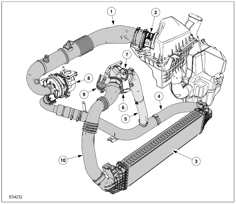
1 Connecting piece between air cleaner housing and turbocharger
2 Combined IAT and MAF sensor
3 Intercooler
4 Connecting piece between turbocharger and intercooler
5 Intercooler bypass
An intake manifold flap housing has been added to the intake system in conjunction with the particulate filter system. The intake manifold flap housing contains the following components:
• Intercooler bypass flap with vacuum unit,
• Intake manifold flap with vacuum unit,
• MAP sensor,
• IAT sensor (not illustrated).
The intake manifold flap creates the connection between the cooled air from the intercooler and the intake ports of the engine via the intake manifold flap housing.
The intercooler bypass valve creates a direct connection between the compressor side of the turbocharger and the intake ports of the engine via the intake manifold flap housing. The intercooler is bypassed.
Actuation of the two flaps is performed by vacuum, which is controlled by means of two solenoid valves. During the regeneration phase the air mass flowing through the intercooler (regulated by the intake manifold flap) is reduced.
At the same time, the flow of uncooled air mass via the intercooler bypass (regulated by the intercooler bypass flap) is increased.
This reduces the engine’s cylinder charge while keeping the intake air temperatures constant to prevent variations in exhaust gas temperatures during regeneration.
The position of both valves is dependent on the intake air temperature. For this reason, there is an additional IAT sensor in the intake manifold flap housing, downstream of the intake manifold flap and intercooler bypass flap (not illustrated).